In early 2019 I stumbled upon the website http://www.sudomod.com/ where wermy shows off some amazing builds. The GameBoy builds really caught my attention. To add fuel to the fire, I visited the sudomod forum and admired the members very impressive builds. The ability to have thousands of retro games in a portable (raspberry pi powered) handheld was awesome. Since building the project is usually more fun to me than playing the actual games, I decided to build my own GameBoy. I never found an AIO (all in one board) with the features I was after so I decided to start from scratch and create my own PCB's. So instead of doing mods to plastic cases like everybody else was doing, I decided to build a custom aluminum case with the exact layout I wanted. I quickly realized it's pretty tricky to get all the little bits and pieces to fit inside a handheld system compared to a full size arcade machine. It's taken me about 4 months of design time (working on it in my spare time) but I've finally started making some aluminum chips. My background is CNC machining / mechanical design so the case design and prototype is by far the easiest of all the task for me. I've only created basic PCB's in the past so creating the PCB's for this design will be a good learning experience.
A few of the features of the Metal PiBoy are:
- Raspberry Pi Zero or Zero W
- Micro usb power in to power and charge the battery
- HDMI out so you can connect it to your tv and play with a wireless or wired gamepad
- Two power switches. 1) Main power and 2) screen power so the screen can be turned off while connected to a tv.
- Three LED indicators on top to show the states of: power on, charging, charge full
- Stereo speakers with volume wheel plus audio out via head phone jack
- USB port for gamepad, keyboard, etc.
- Secure no external access to SD card. Easy access to SD card when case is opened.
- 3.5" TFT LCD screen with 5/64 thick plexiglass screen protector
- Four buttons on the rear of the case
- Pin hole for power reset
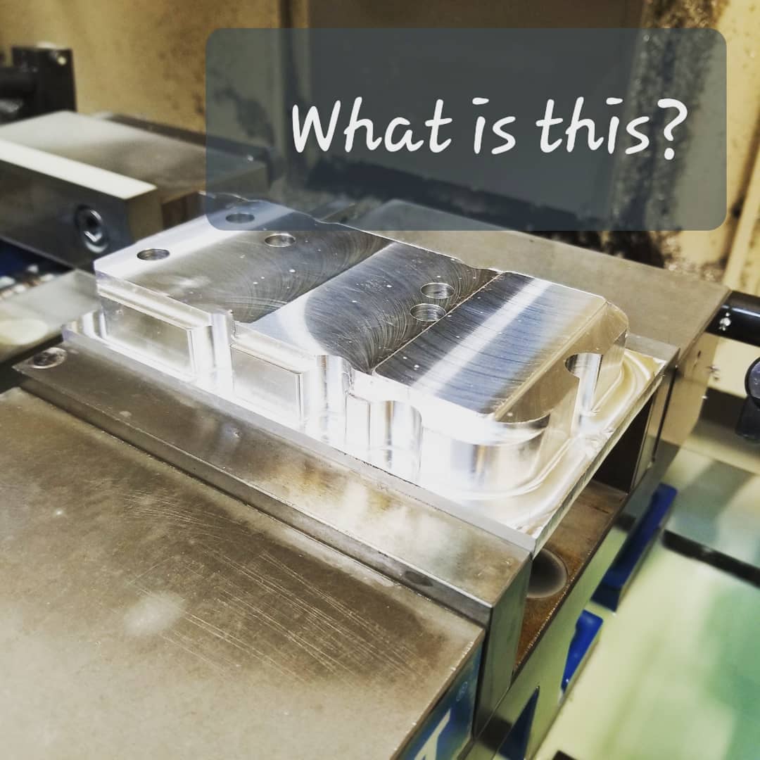
1st operation (Front Housing)
 |
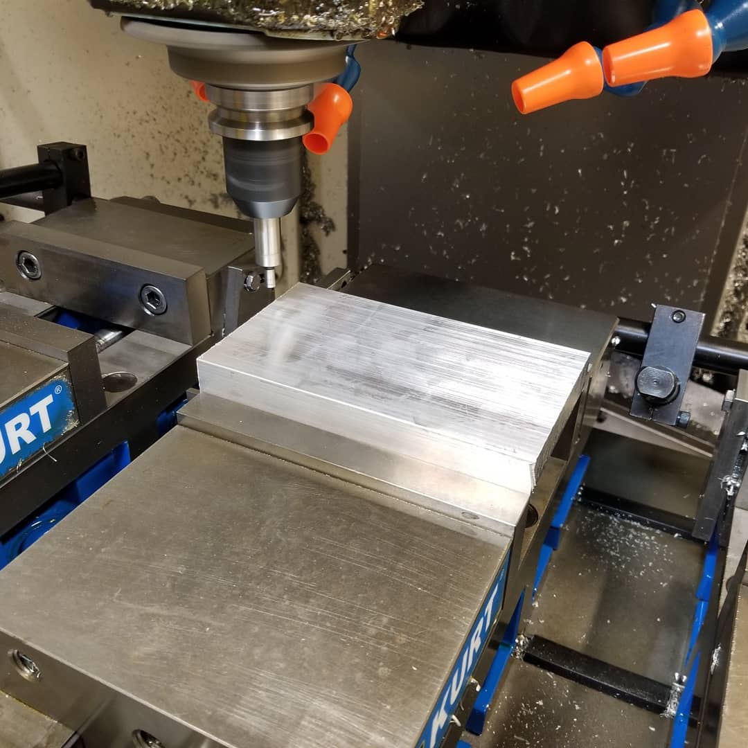 |
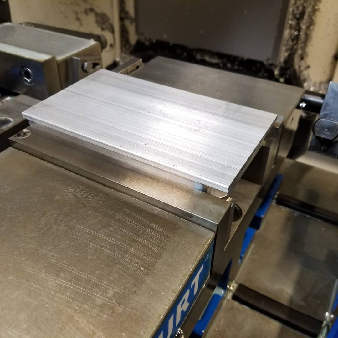
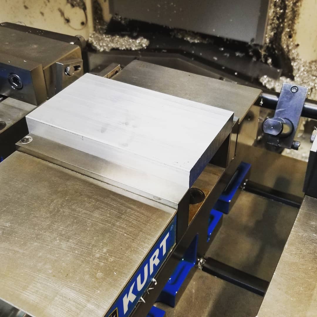
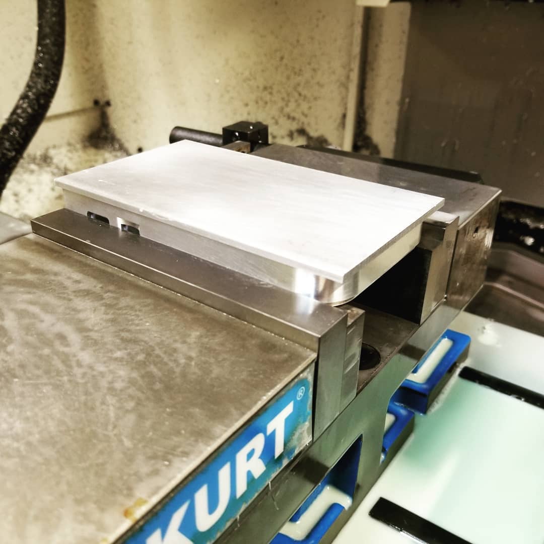
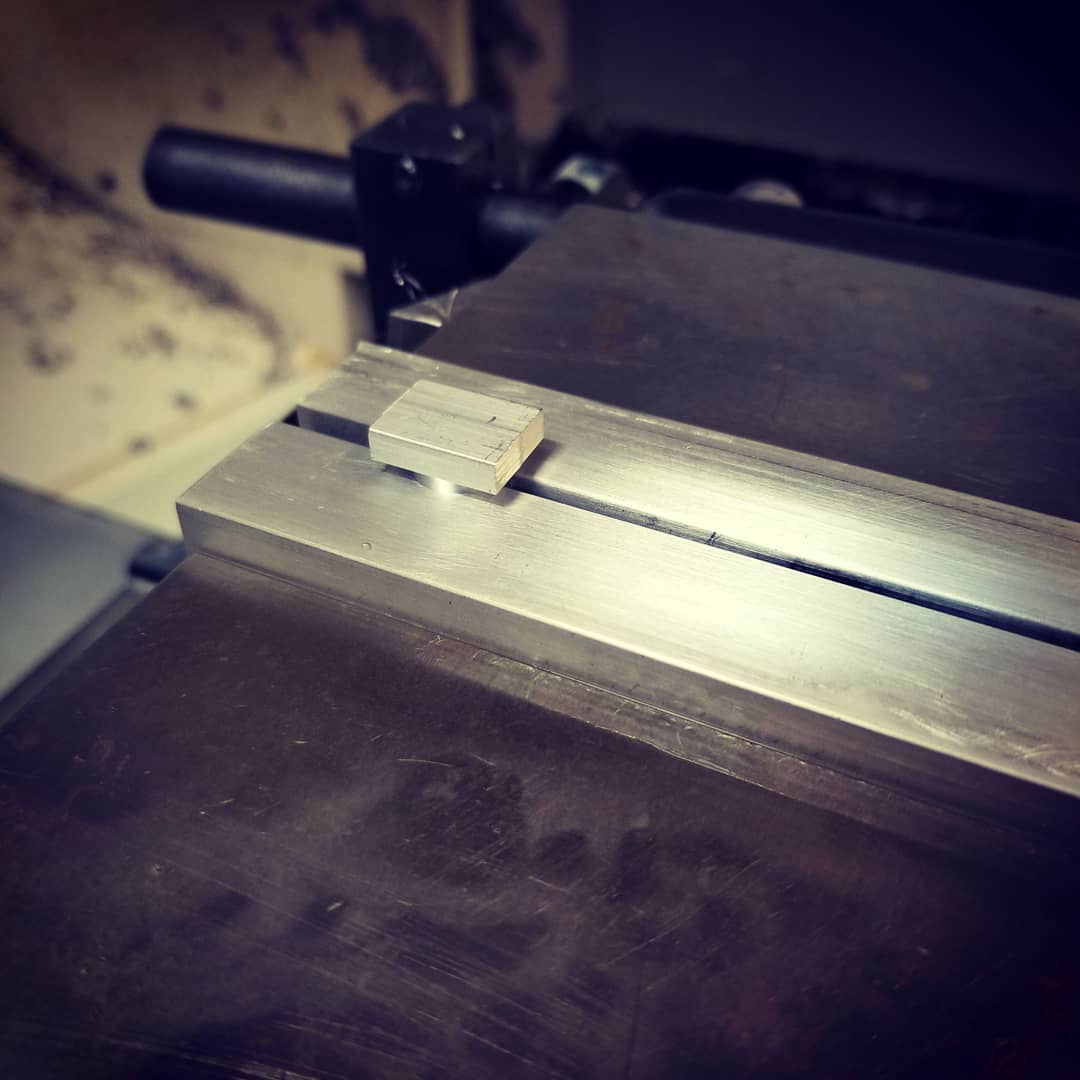
Starting with a piece of 3.5 x 0.75 x 6.0 billet aluminum. In the pic above you can see I'm using an edge finder to locate the X.0 Y.0 fixture offset location.

The 1/2 hog endmill roughed the profile.
1st operation finished.
 |
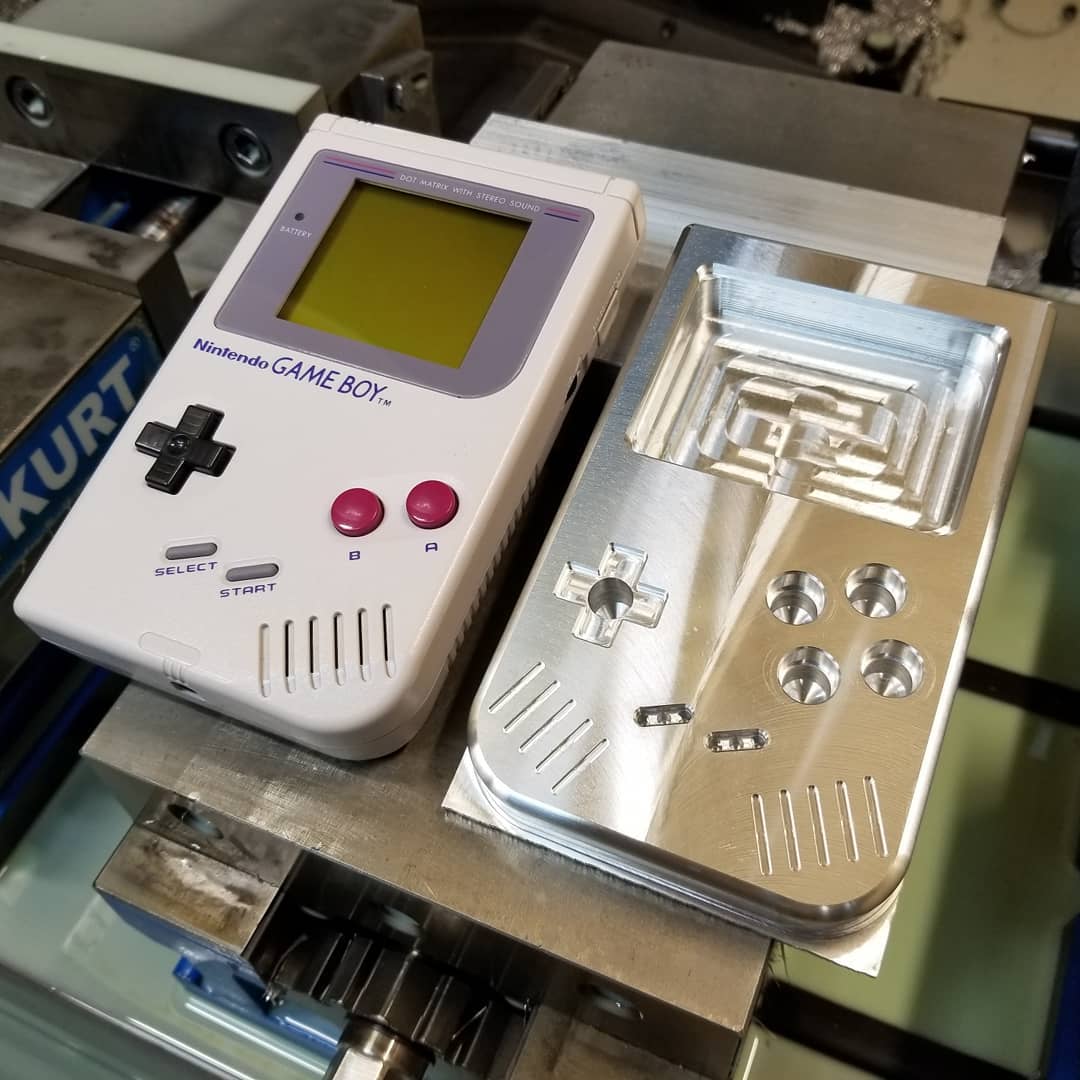 |
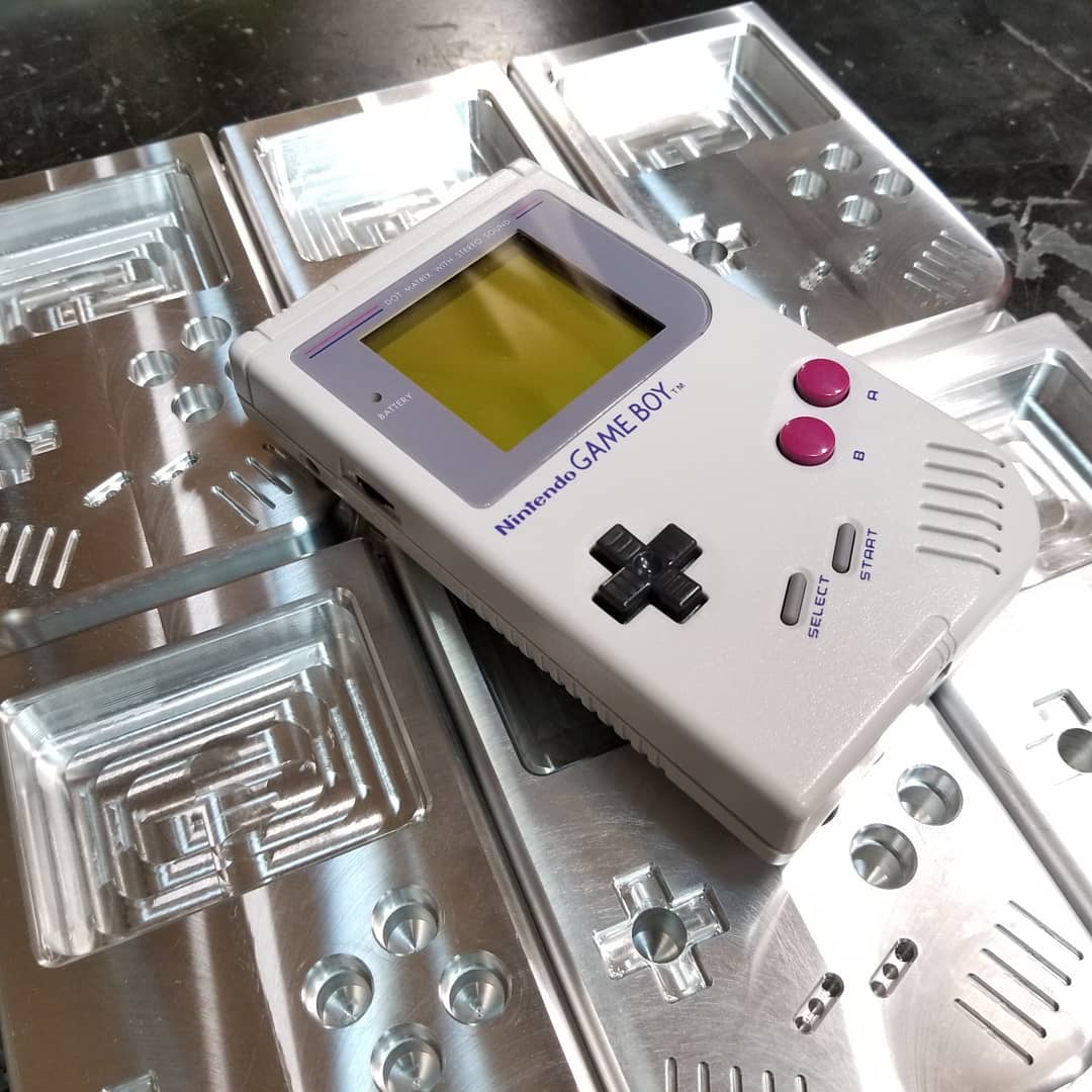
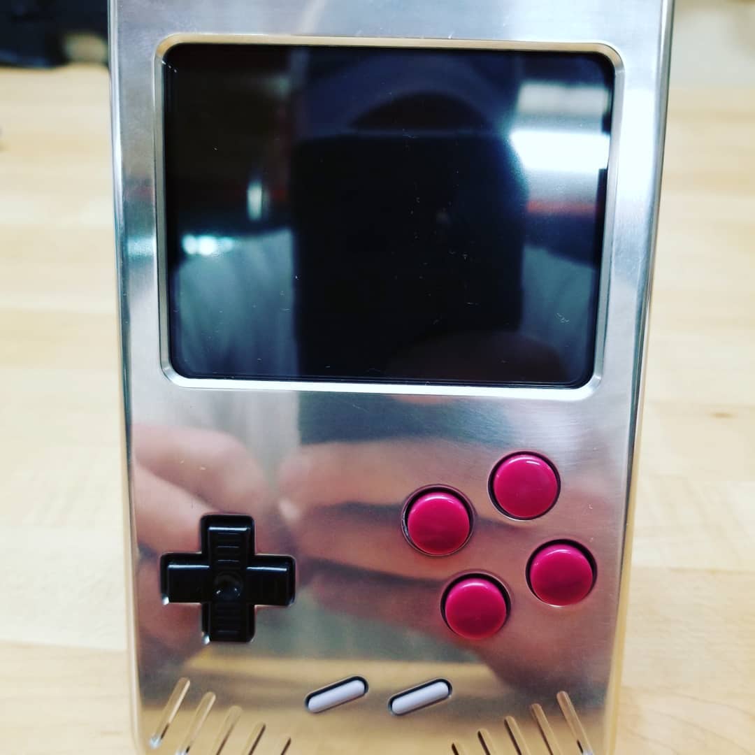
Compared side by side with the 30 year old original GameBoy.
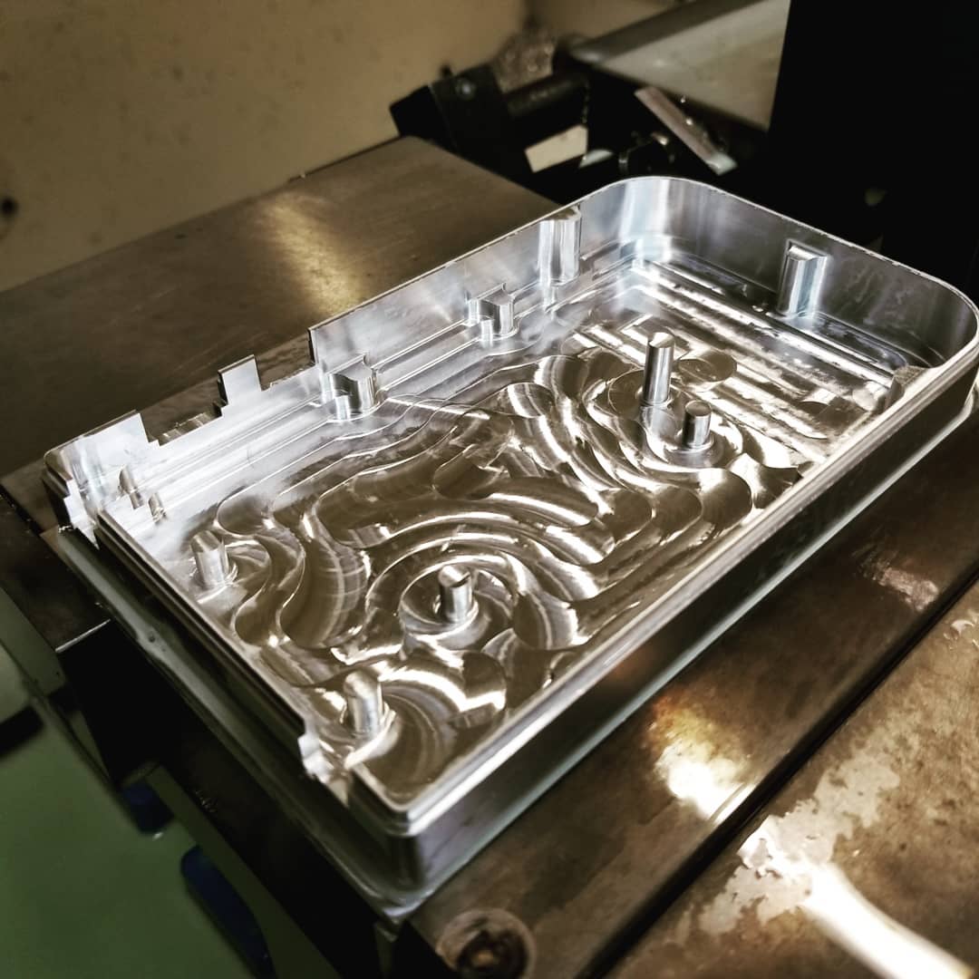
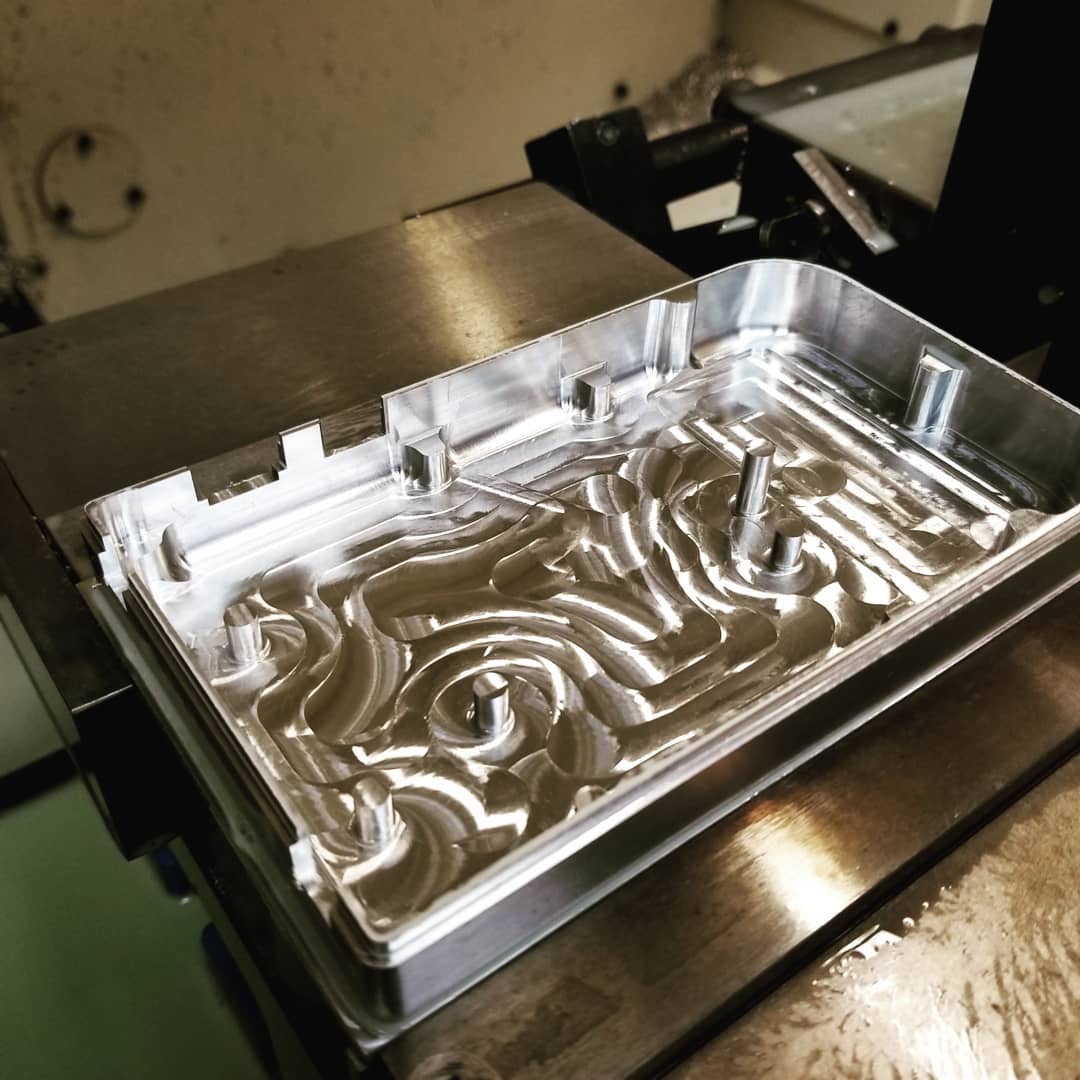
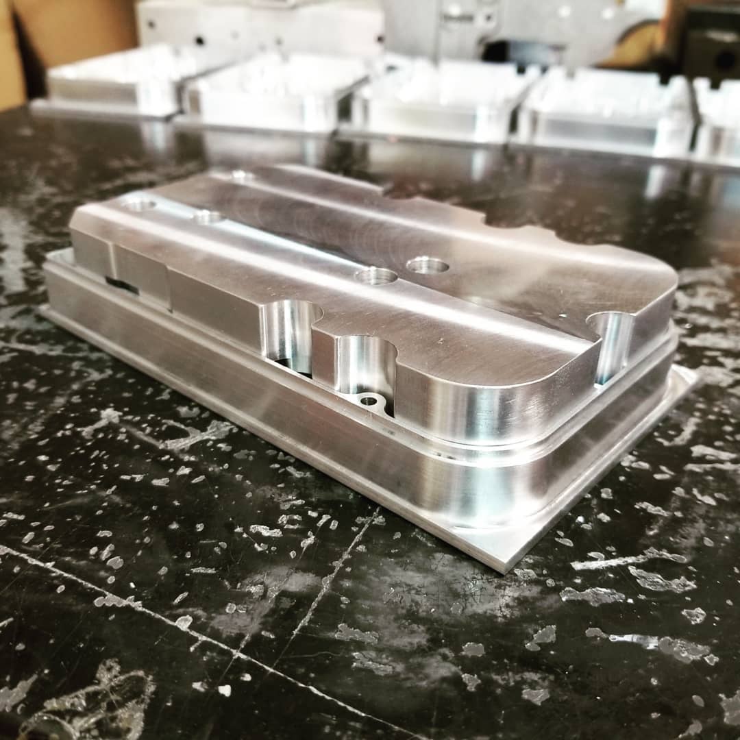
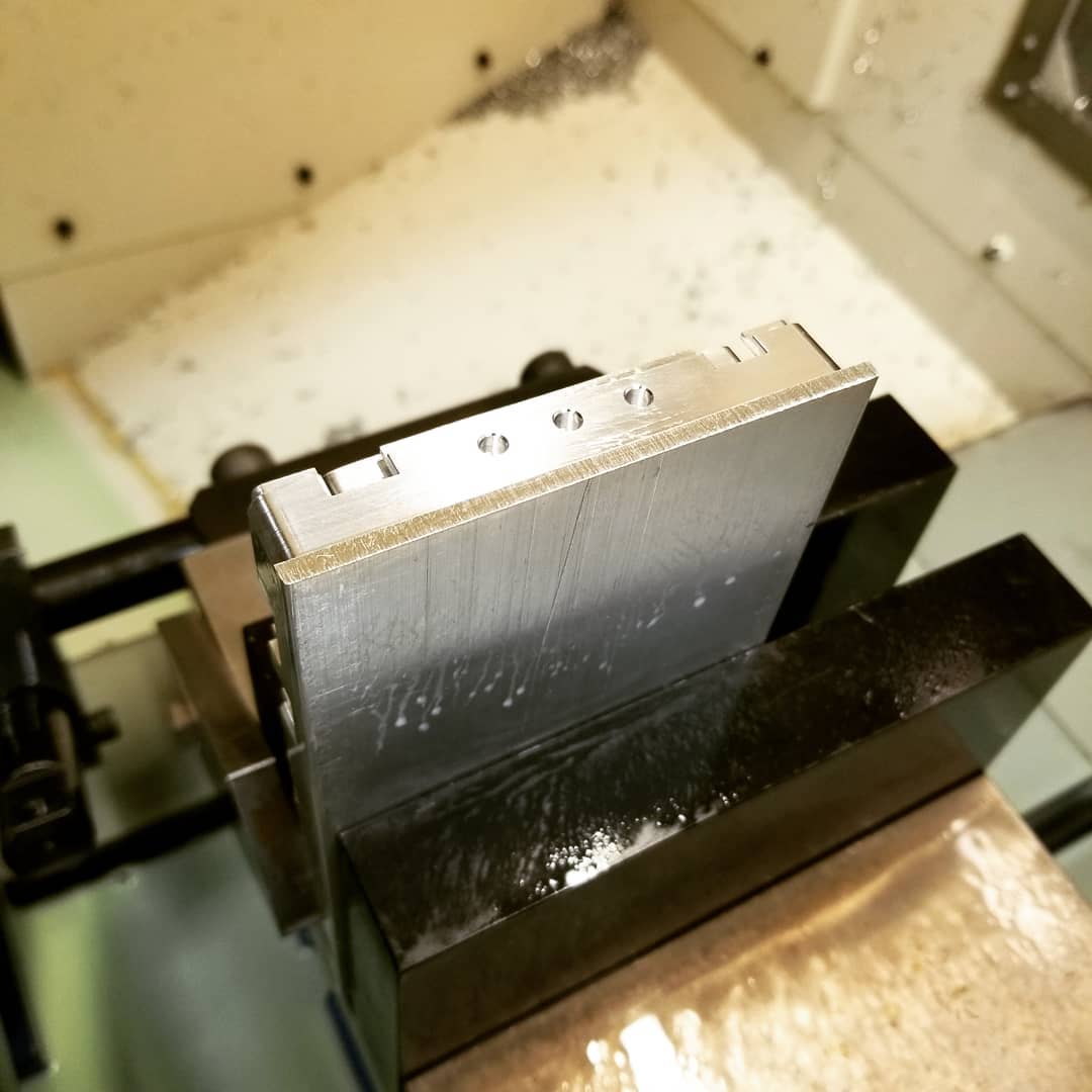
2nd operation (Front Housing)
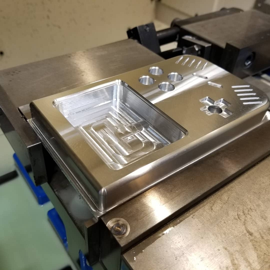
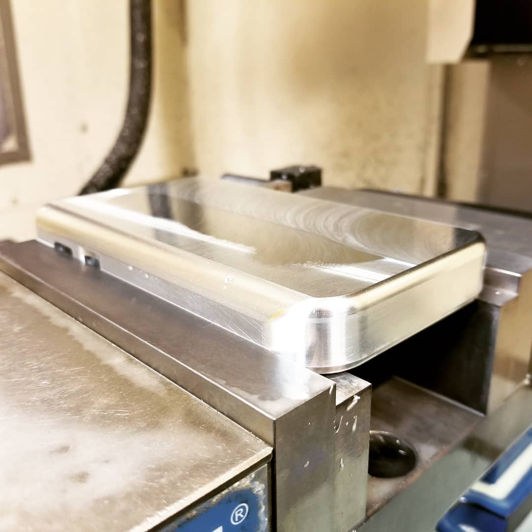
The 2nd operation will be finishing the inside of the front housing.
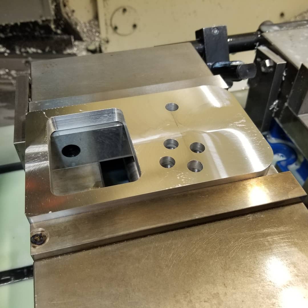
The 3" shell mill brings the material to the correct thickness.
The 1/4" hog endmill makes some rough passes to bring some of the bosses to the correct height.
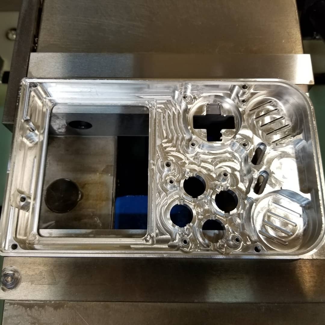
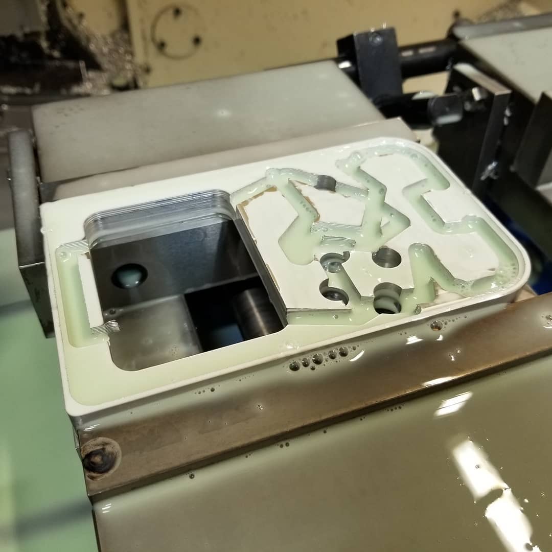
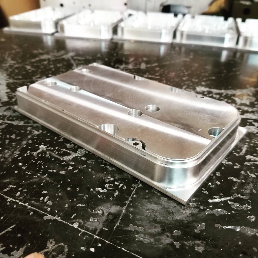
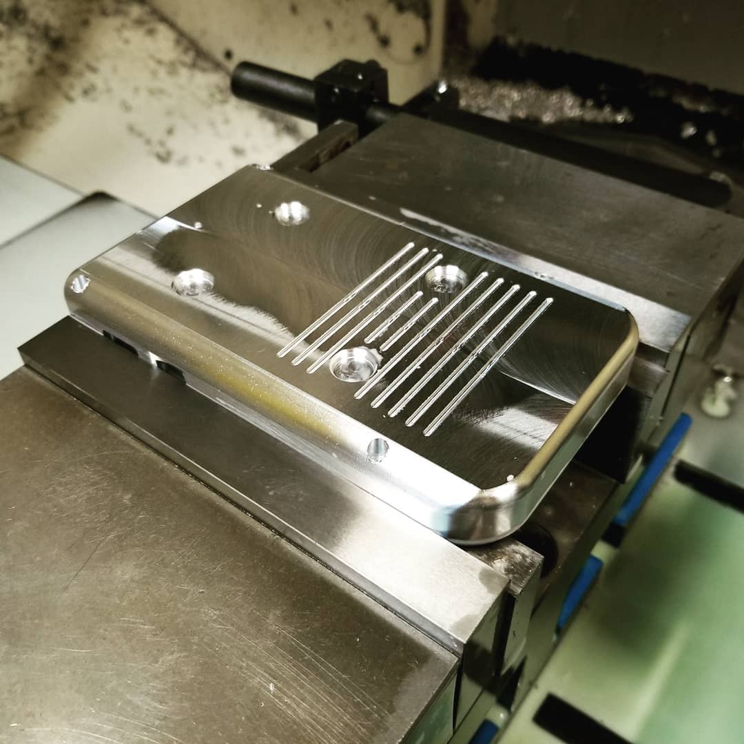
2nd operation is finished. There is lots of little detail machining involved around the ABXY buttons. It took a combination of the 1/2, 1/4, 1/8, 3/32, and 1/16 diameter cutters to make all the detail cuts.
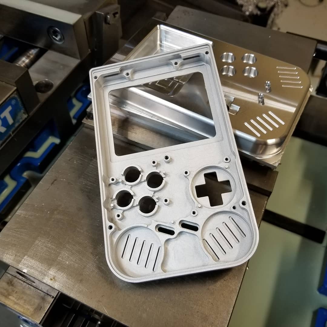
I bead blasted one of the front housings so you can better make out the little detail cuts.
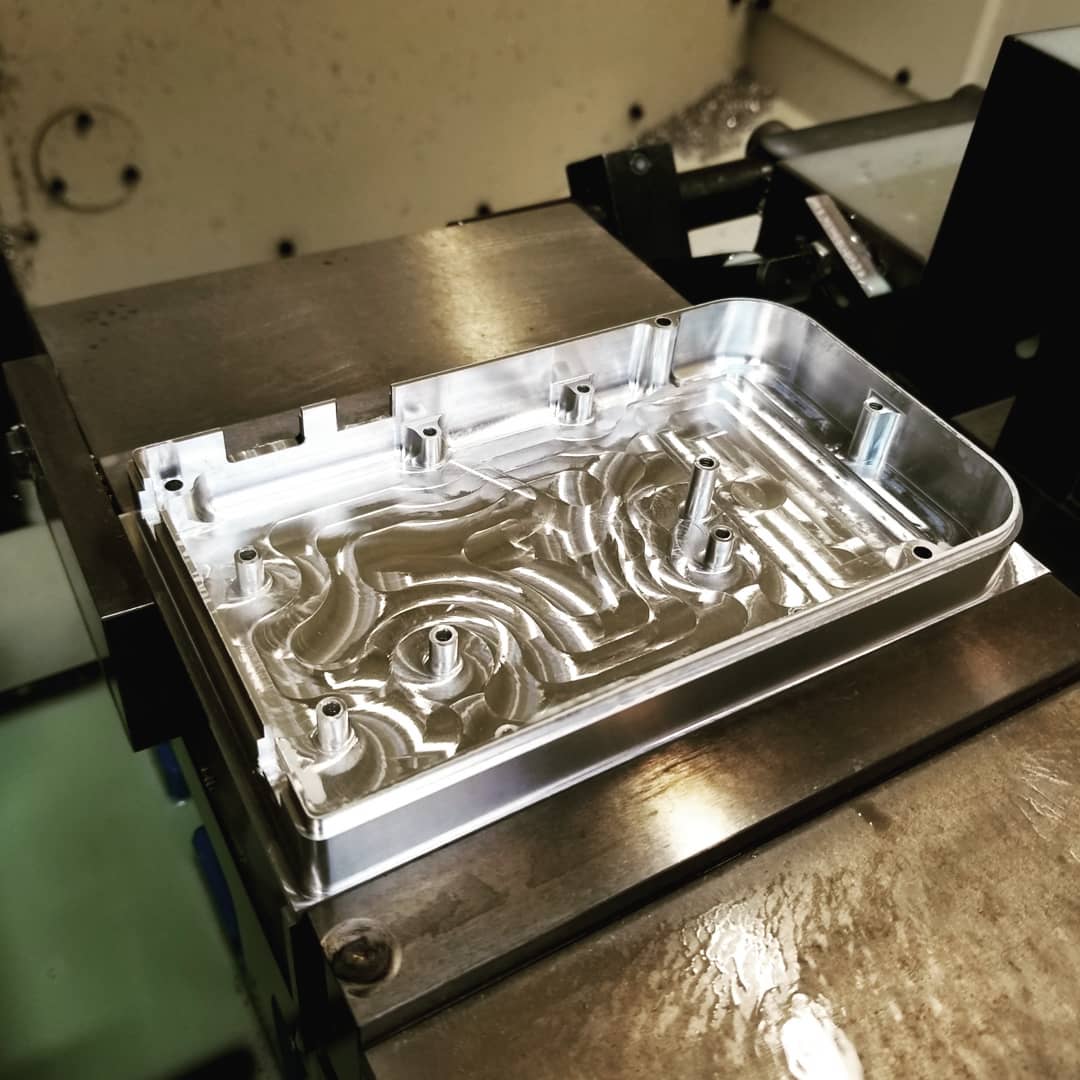
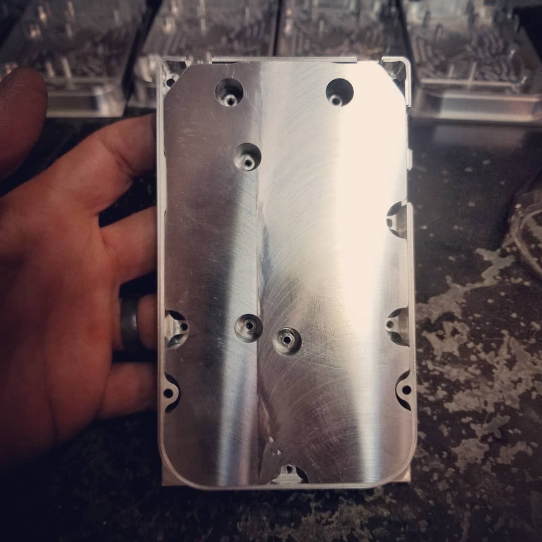
3rd operation (Front Housing)
The only tool used on the 3rd operation was the 1/8 endmill to contour the hole for the head phone jack.
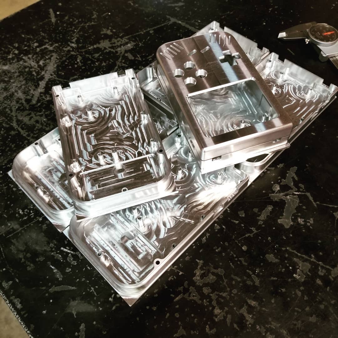
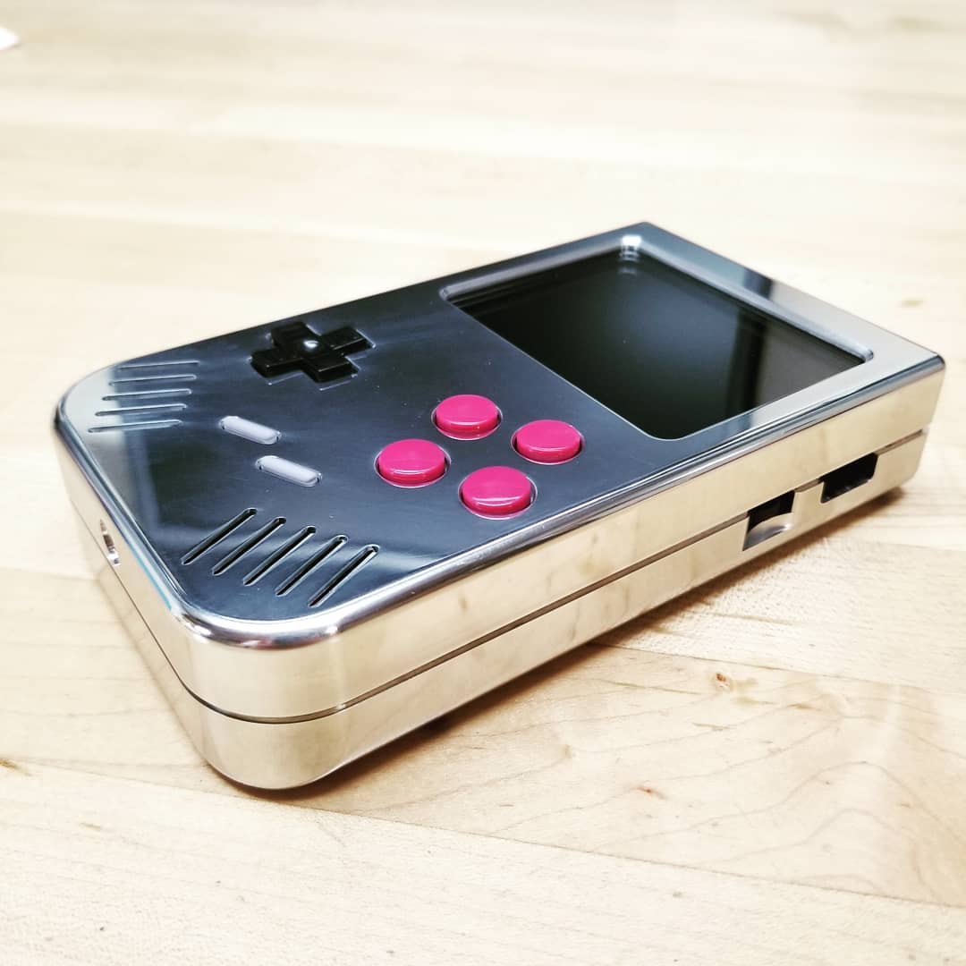
So the front housing is finished for now. I may later go back and add some text to the front housing for buttons and a logo, but for now it's time to move on to the back housing.
Mock-up assembly (Front Housing)
 |
 |
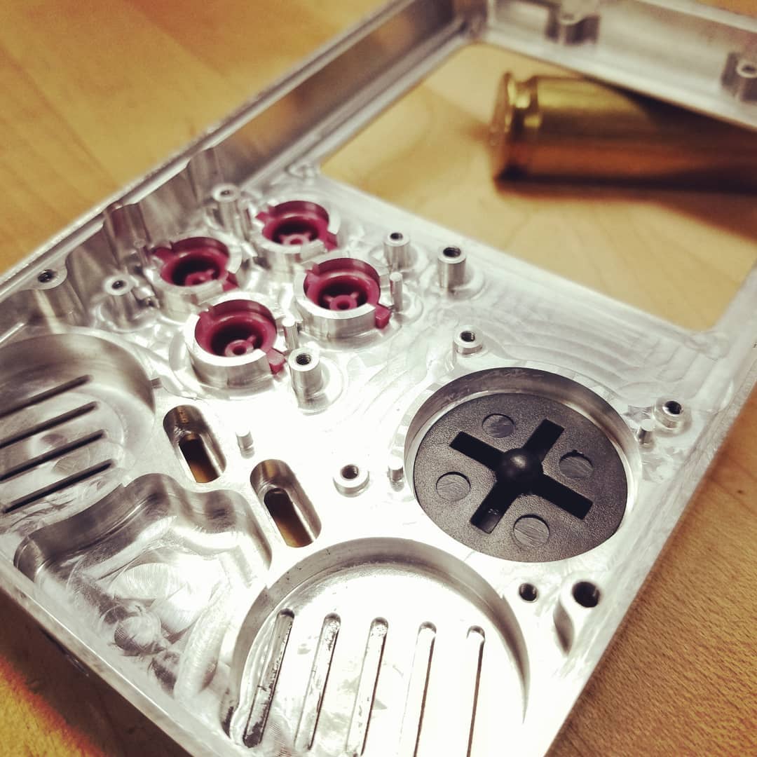
Here you can see the controller buttons and silicon pads installed. Everything fit perfectly. You can also see the 5/64 plexiglass screen protector.
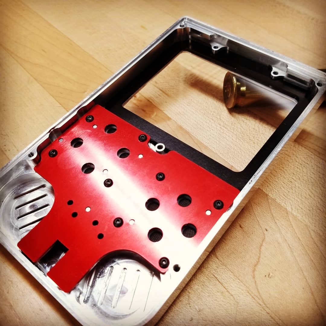 |
 |
There is a laser cut aluminum sheetmetal spacer (black anodized part) between the screen protector and the actual screen. This spacer acts as a buffer zone in case the screen takes a hard hit. The blue anodize sheetmetal part is the clamp that keeps the screen assembly in place. I also laser cut a dummy PCB (red anodized part) to test the hole locations of everything.
 |
 |
 |
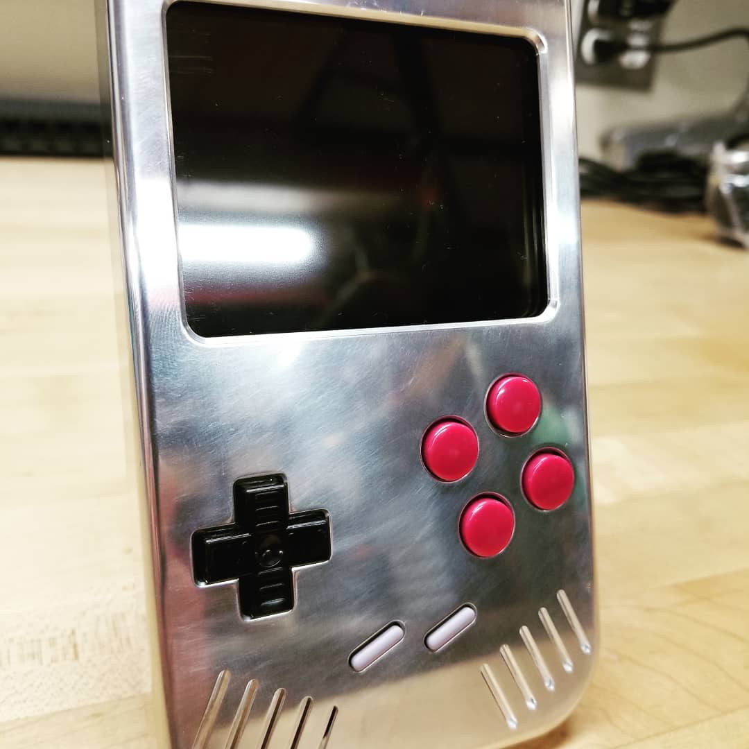
I did a quick 5 minute sand / polish job on the front housing. So far I'm very happy with the way this thing is turning out.
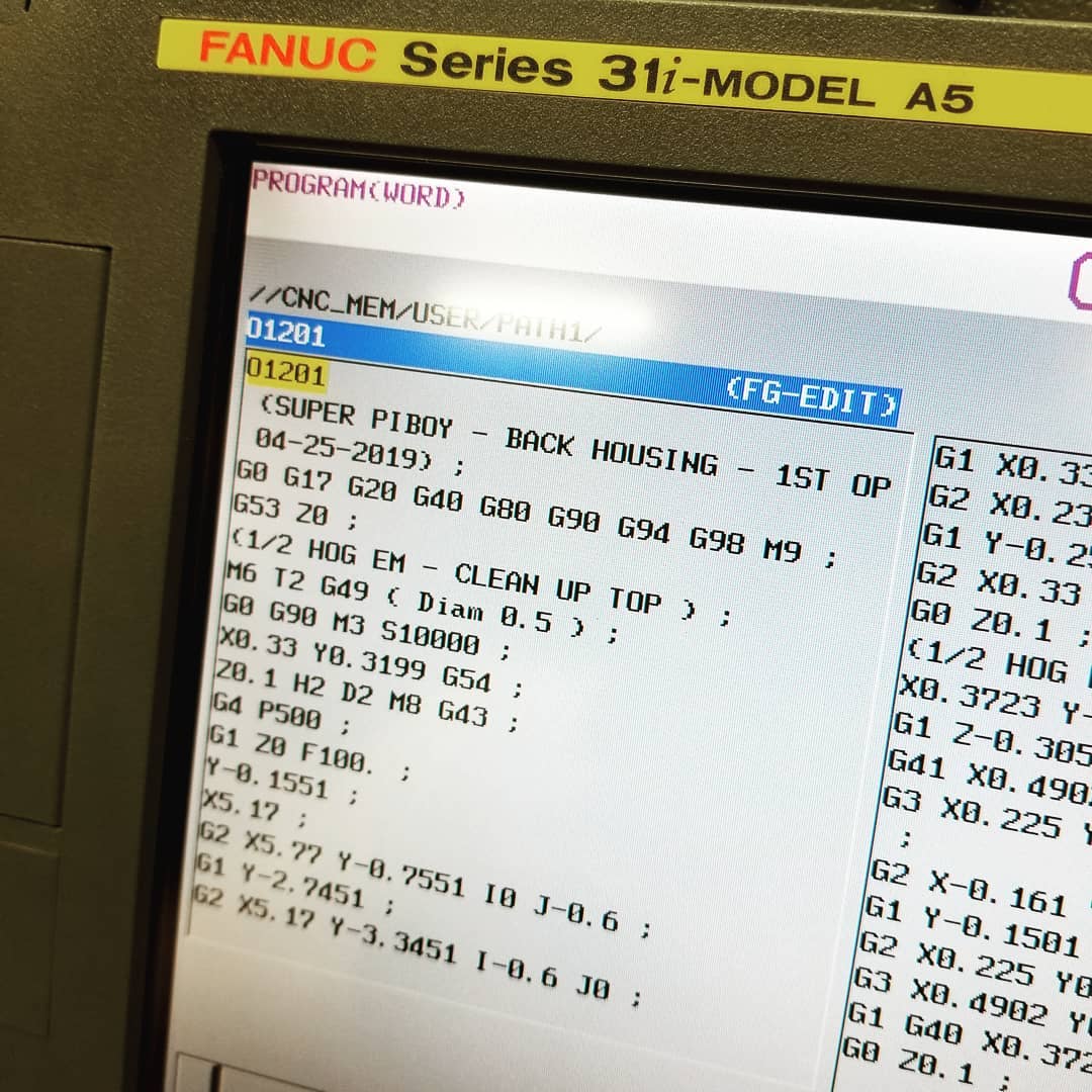
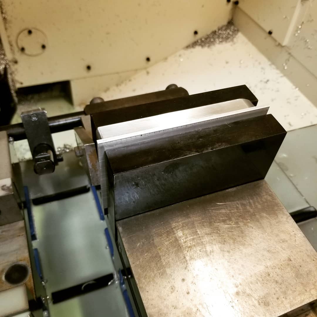
1st operation (Back Housing)
 |
 |
Again, I'm starting with a piece of 3.5 x 0.75 x 6.0 billet aluminum.
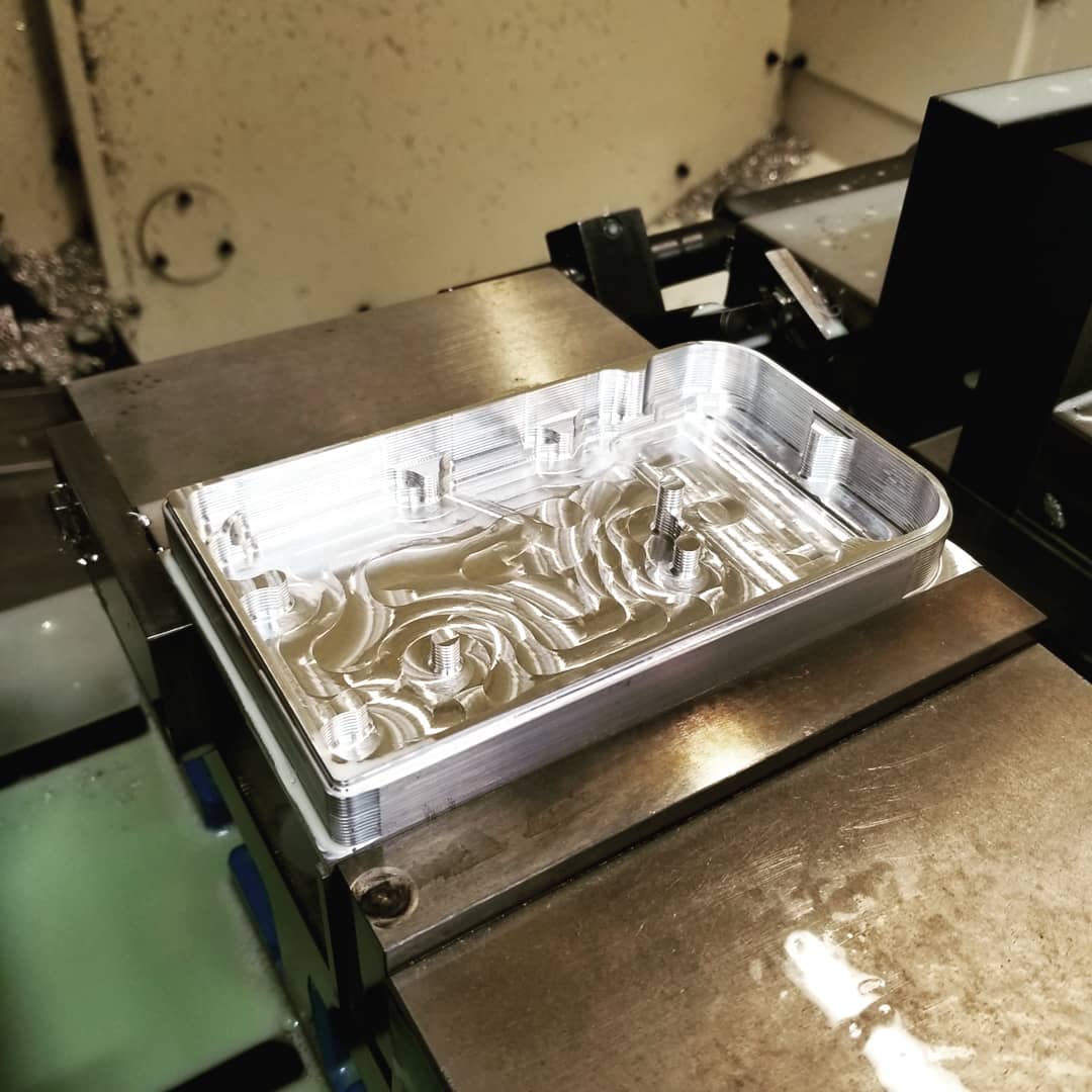
The 1/2 hog endmill roughs the inside of the rear housing.
Since the left and right sides of the rear case have large radii, I need to add a radius to the inside corners so it doesn't bust out. Above you can see before and after the 1/4 ball nose endmill runs.
 |
 |
 |
The 1st operation of the rear housing is now finished.
Insert (Back Housing)
In order to keep the housing rigid during the remaining cutting operations, I needed to create an insert that fits the housing perfectly. This insert will be used on the 2nd, 3rd and 4th operations.
 |
 |
 |
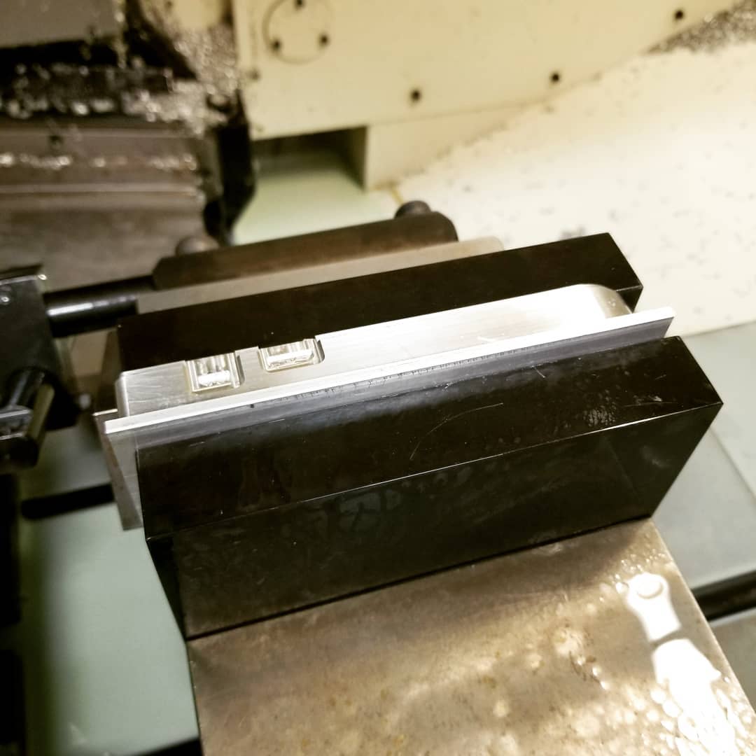
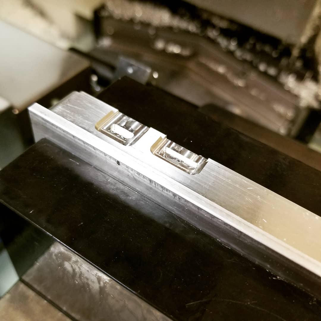
2nd operation (Back Housing)
 |
 |
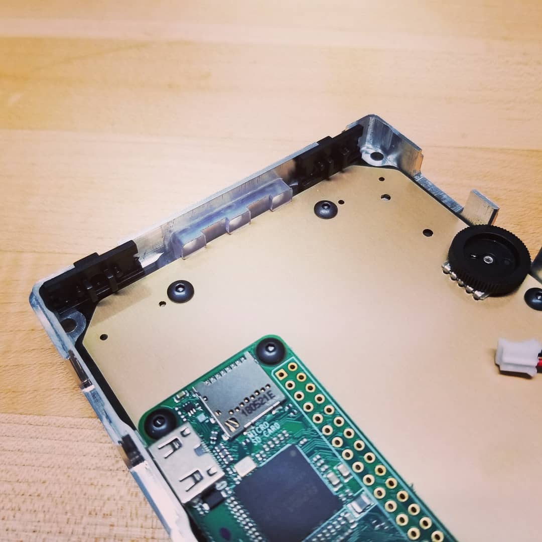
For the 2nd operation, I drilled the 3 LED indicator holes on top of the case. I will machine a clear plastic part that will set inside these holes and line up with the circuit board so the SMD LED's can shine through the holes.
3rd operation (Back Housing)
 |
 |
 |
The 3rd operation cuts the slots for the micro USB and HDMI ports.
4th operation (Back Housing)
 |
 |
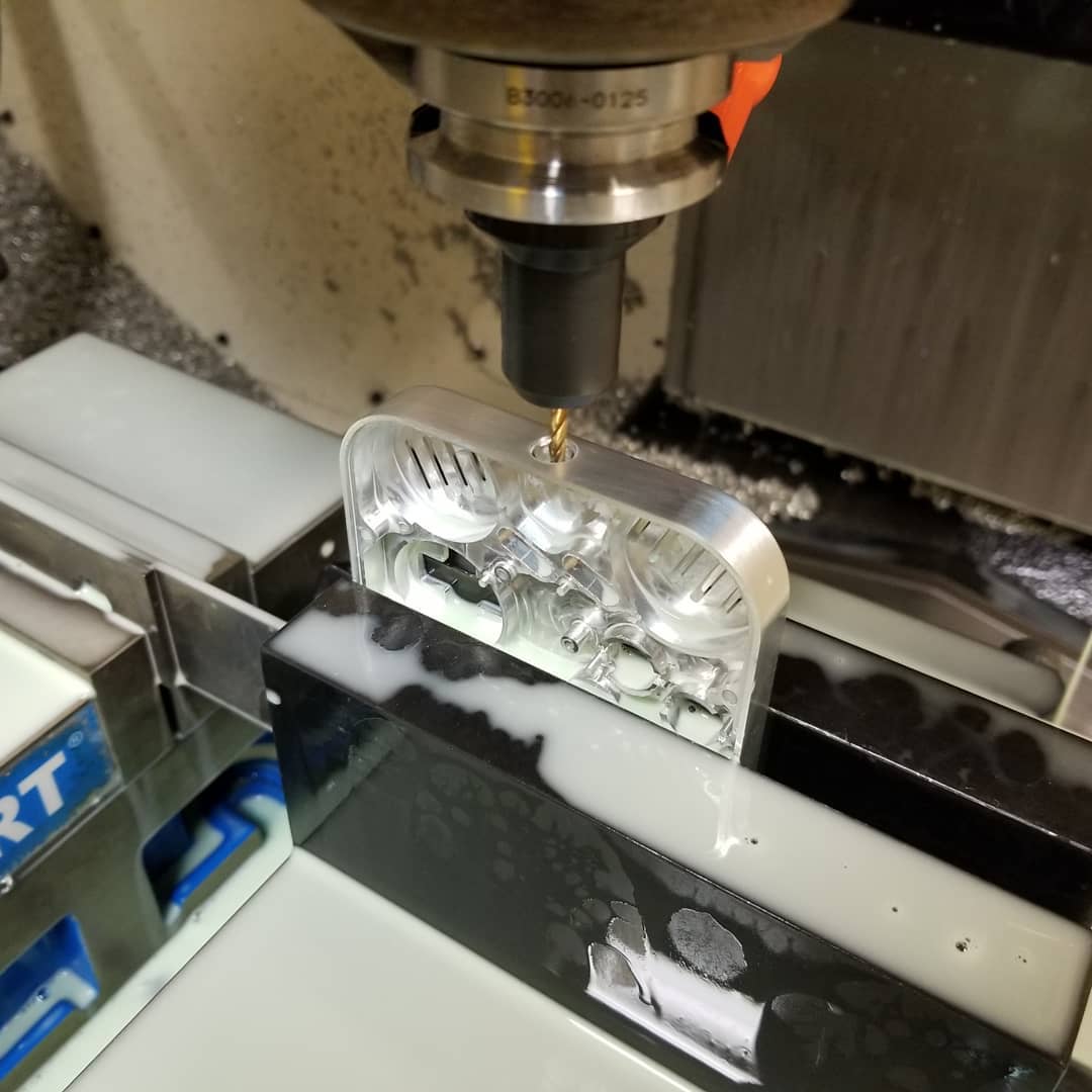
The back of the rear housing there is a small radius that blends into a larger radius. This will require some 3D profile machining. I ended up using a 0.005" step over for each pass. The total number of g-code lines for this 3D profile alone was 189,999 lines. During this cutting, the machine was processing 158 lines per second.
 |
 |
The 3" shell mill brings the part to the correct thickness and the 1/4 ball nose endmill does the 3D profiling.
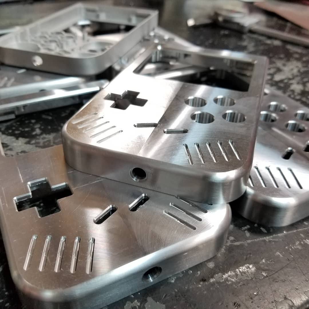
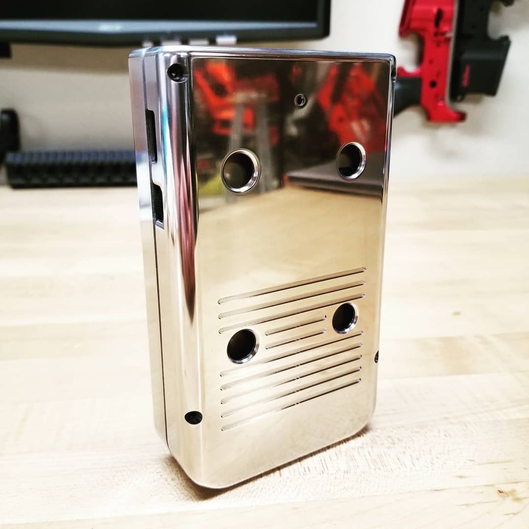
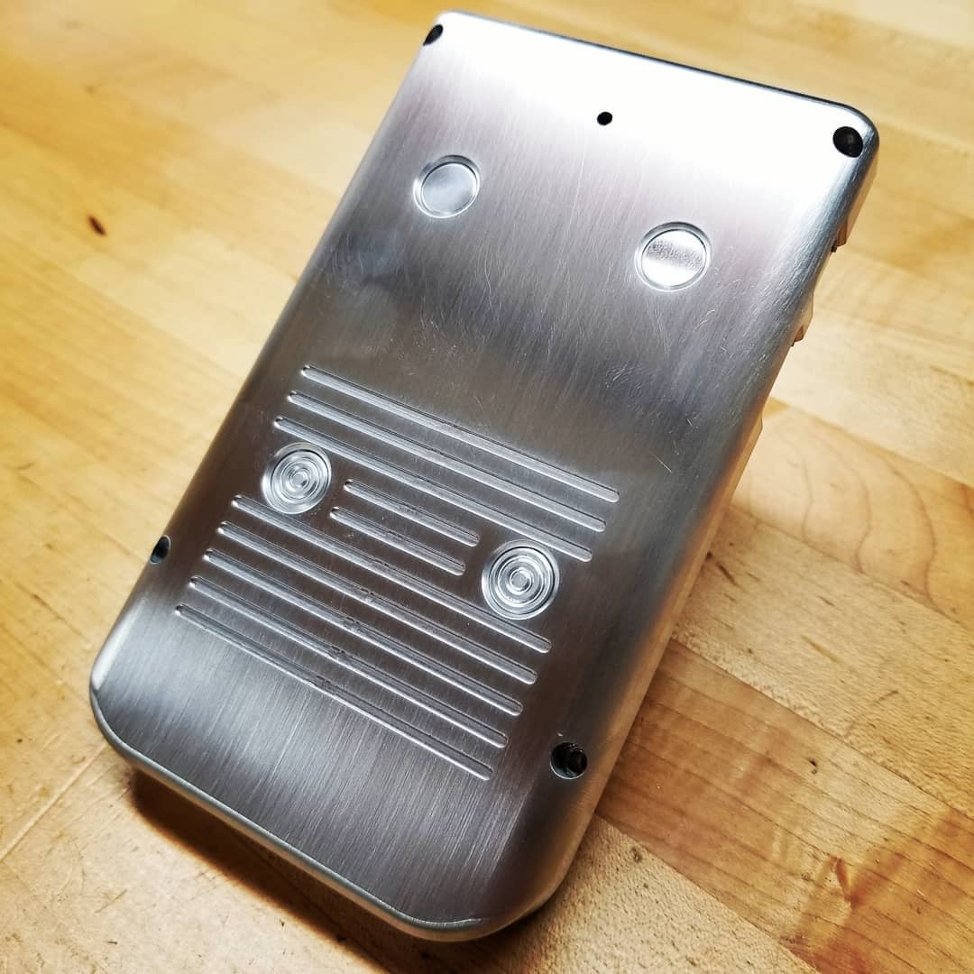
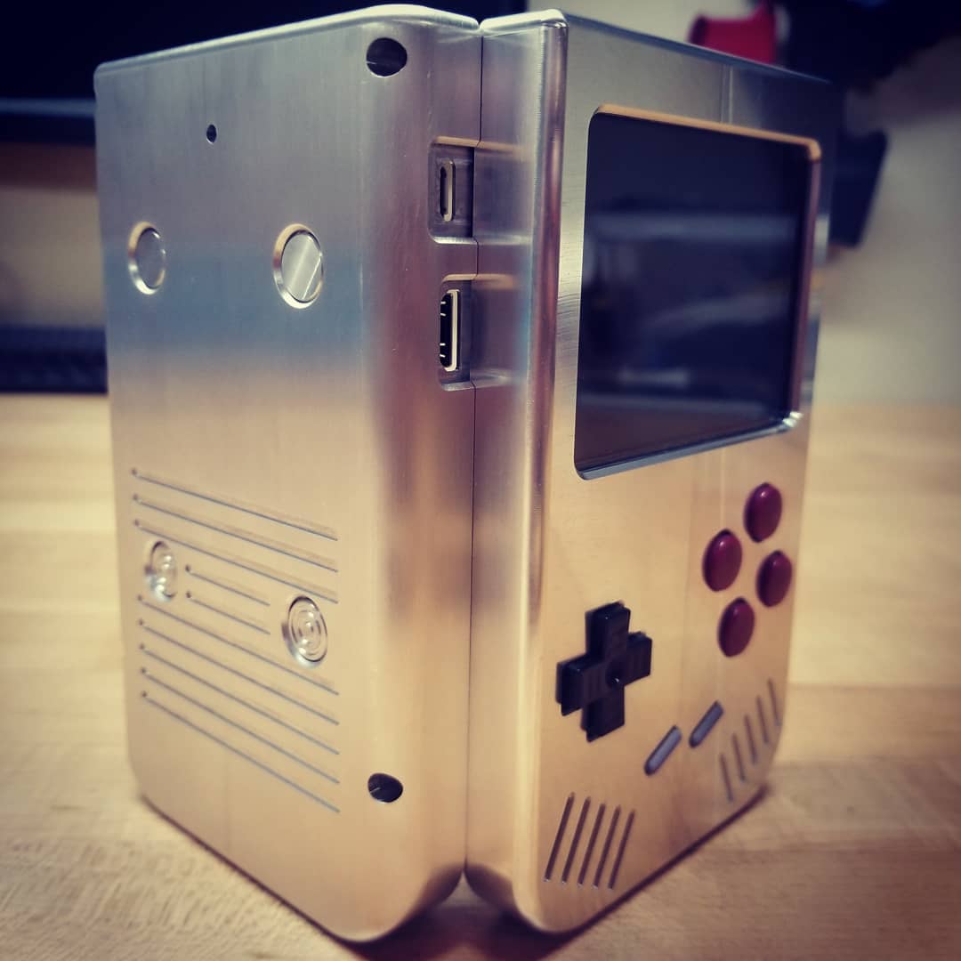
The back housing is now finished. You can see the 4 button locations on the back of the case. You can also see the pin hole for the power reset. I also added some small grooves to give better traction while holding the case similar to the original GameBoy DMG case.
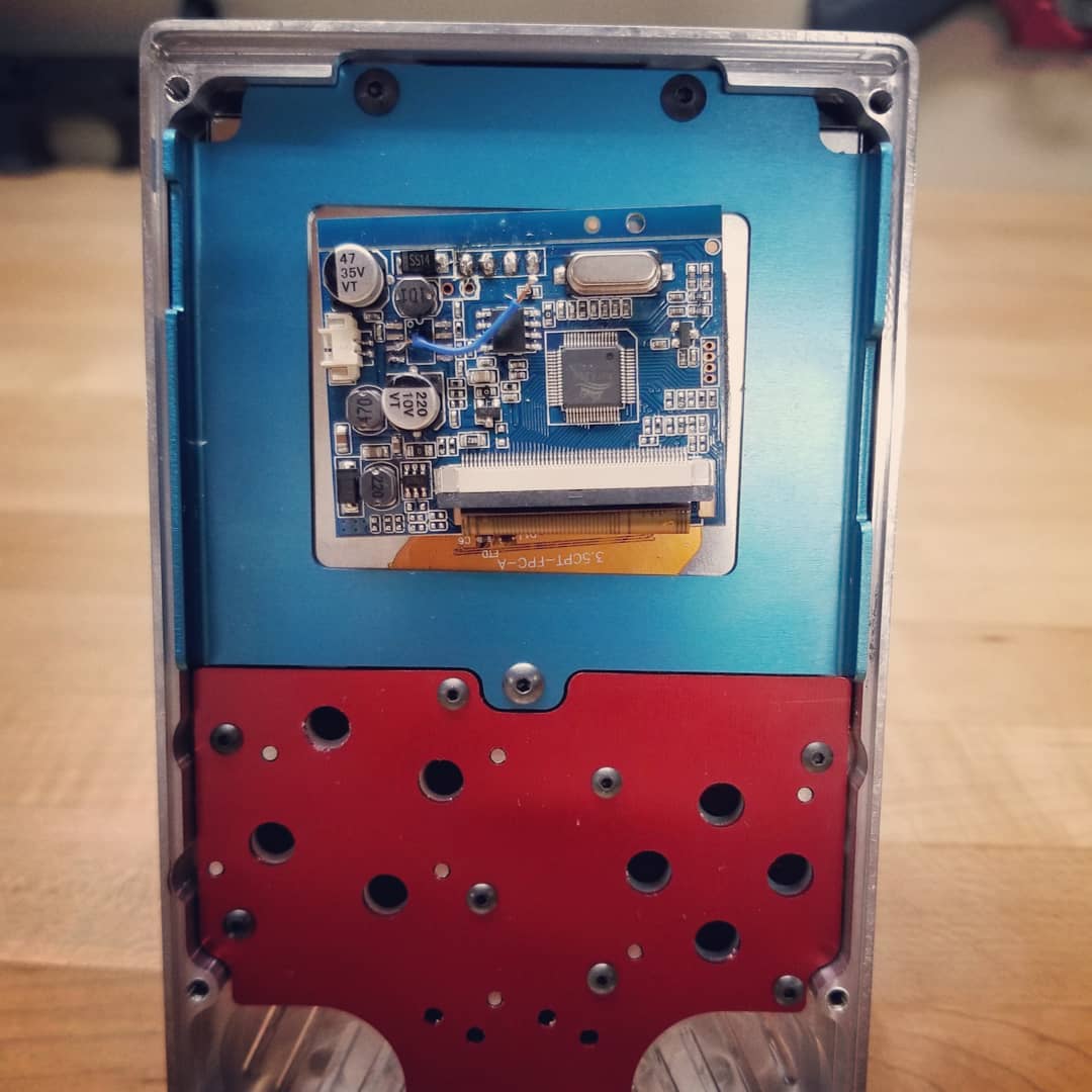
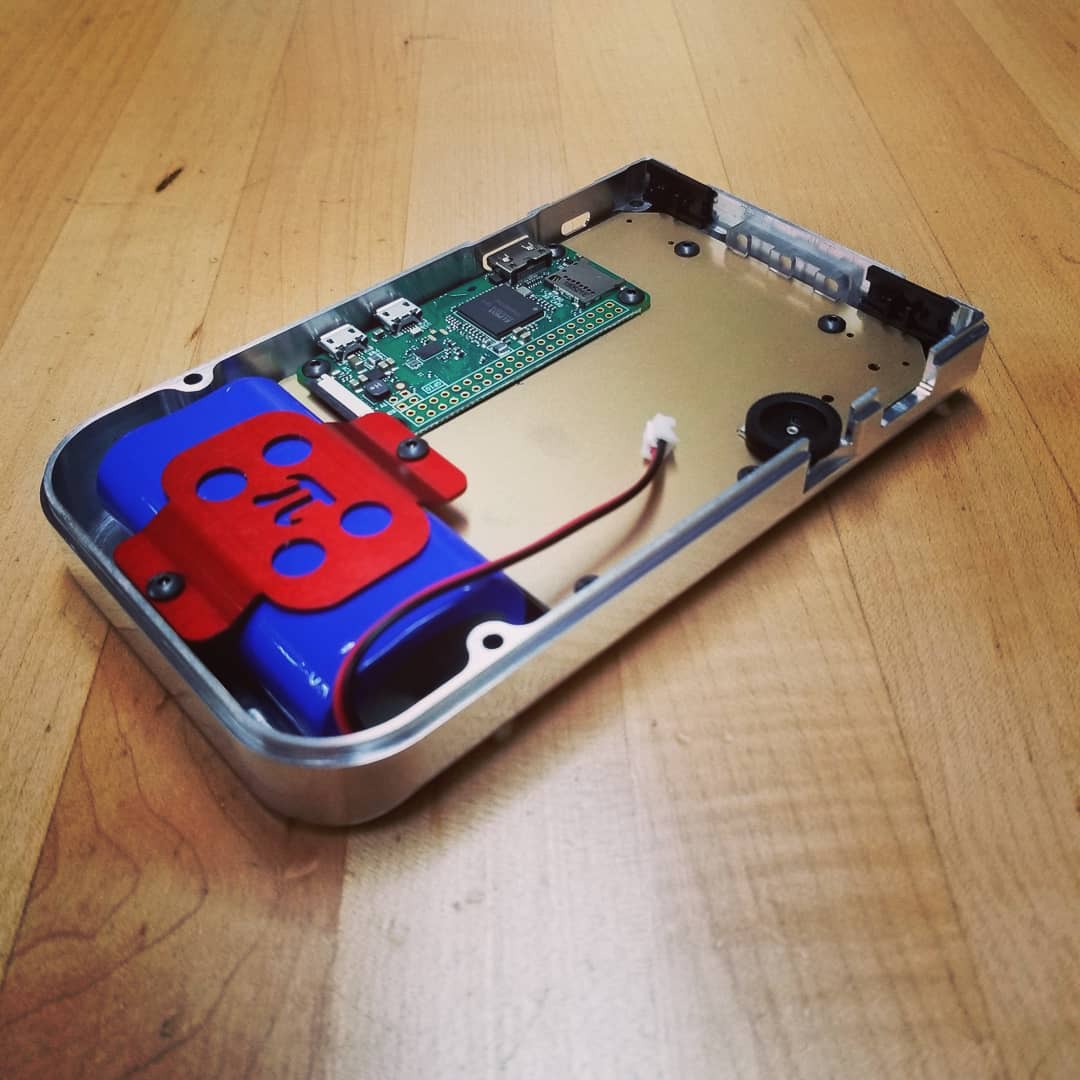
Mock-up assembly
I done another mock-up assembly and so far everything is still fitting together perfectly. I laser cut another dummy PCB board from aluminum to test fit as the power board. It has 2 power switches: 1 for main power and 1 for screen power.
 |
 |
 |
 |
 |
 |
 |
Back housing buttons:
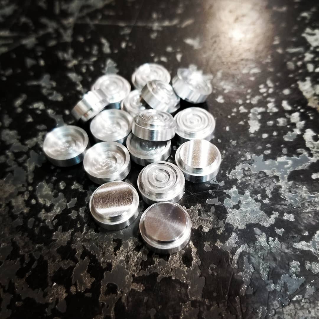
The back housing has 4 buttons: left trigger, right trigger, left shoulder, and right shoulder. There are actually 5 tactile buttons on the back of the power pcb. The 5th top center button is a power reset. This will reset the 5VDC power output in case the Pi gets locked up. I machined the buttons on a CNC mill but future buttons will be turned on a Swiss screw machine. I had to make a set of aluminum soft jaws to hold the round buttons for the 2nd operation.
 |
 |
 |
 |
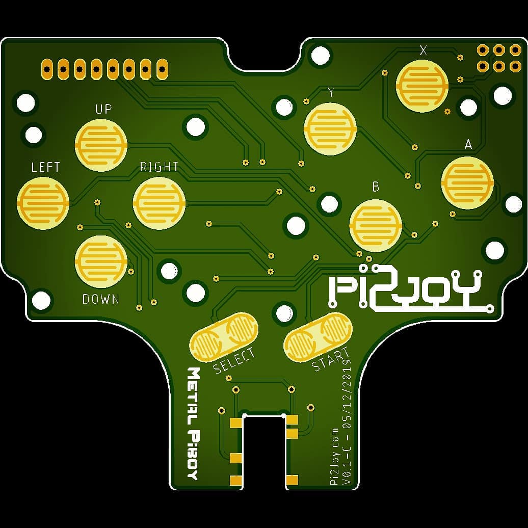
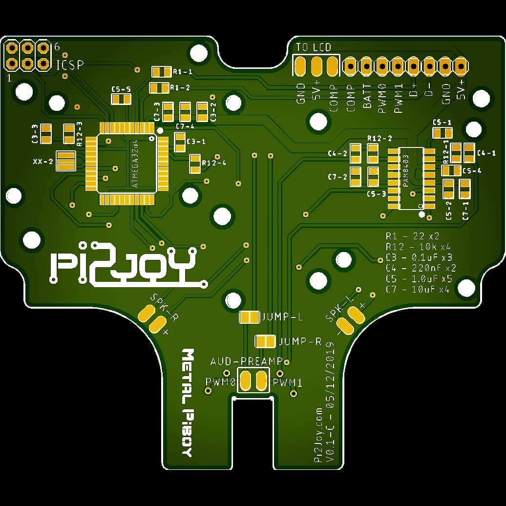
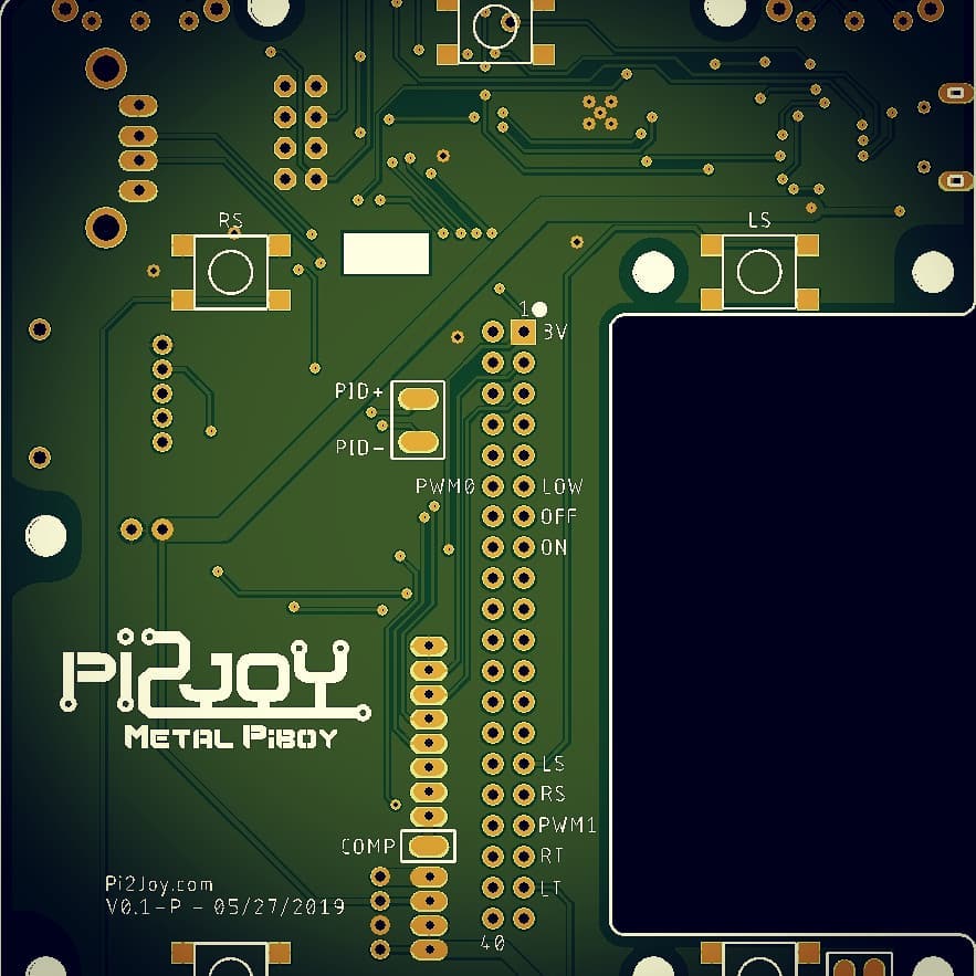
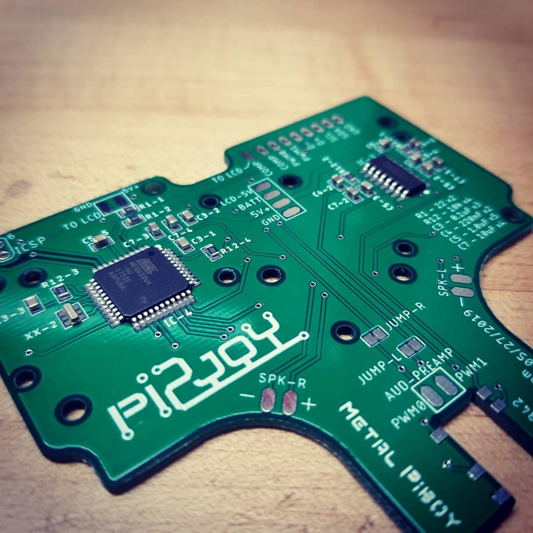
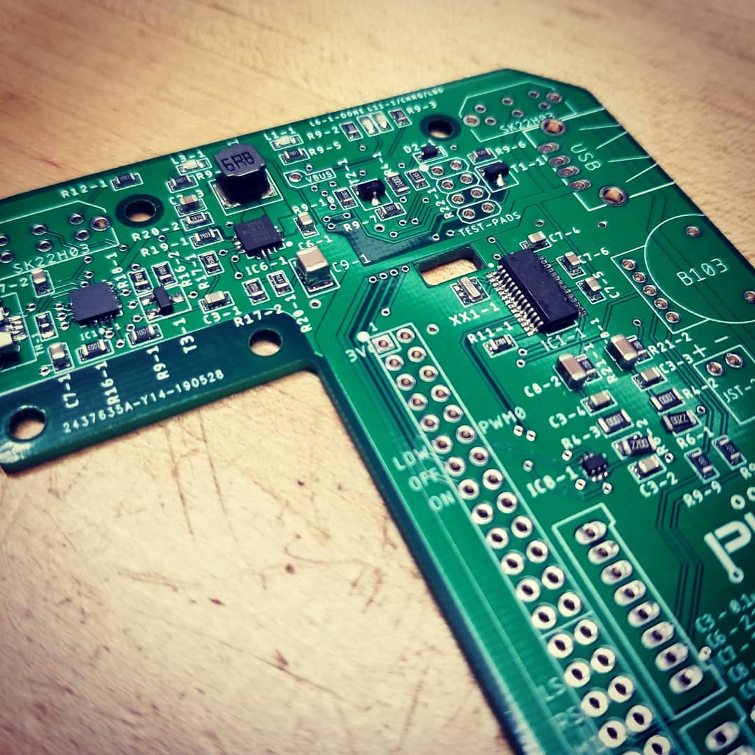
PCB progression:
Below is the board layout of the first version of the control and power boards.
 |
 |
 |
 |
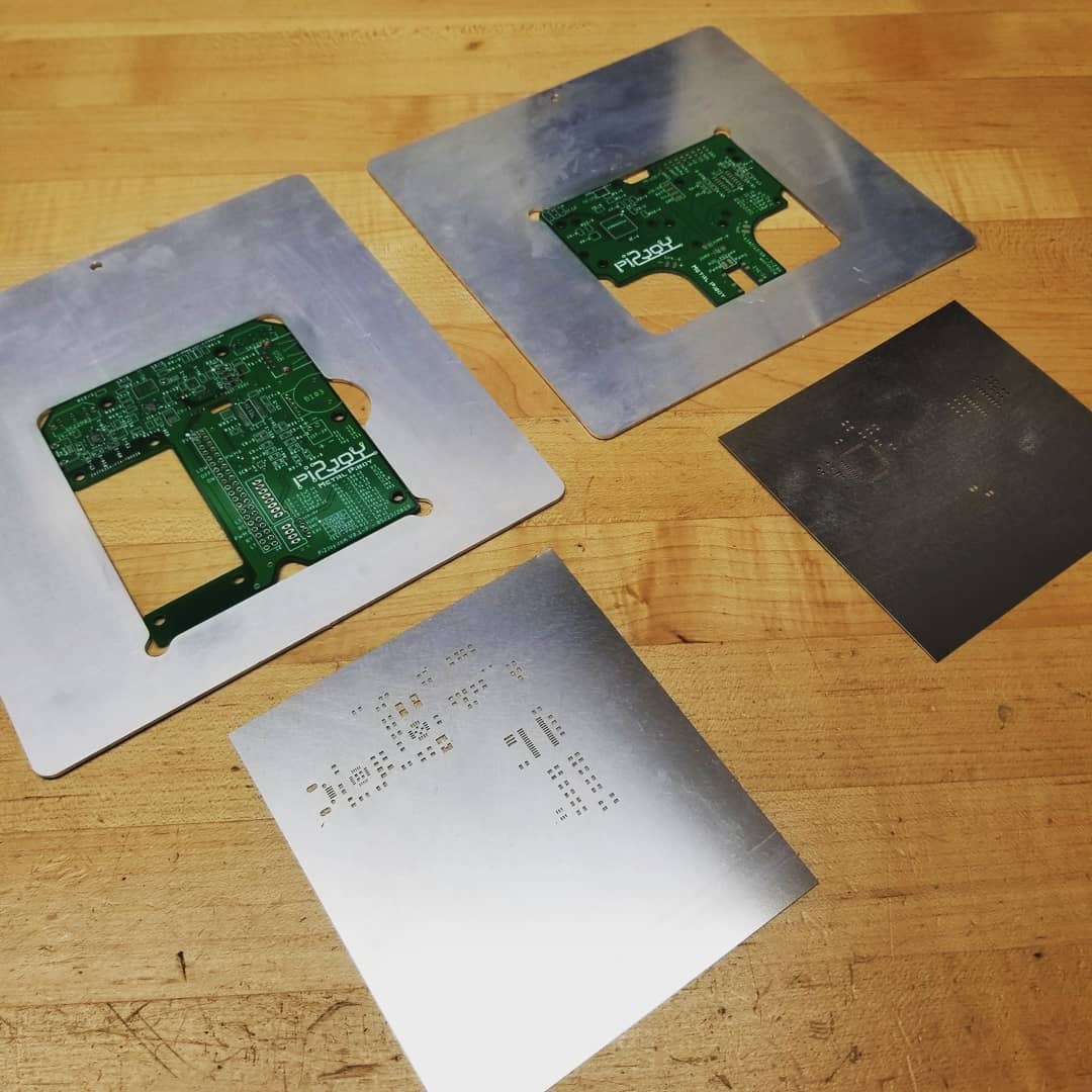
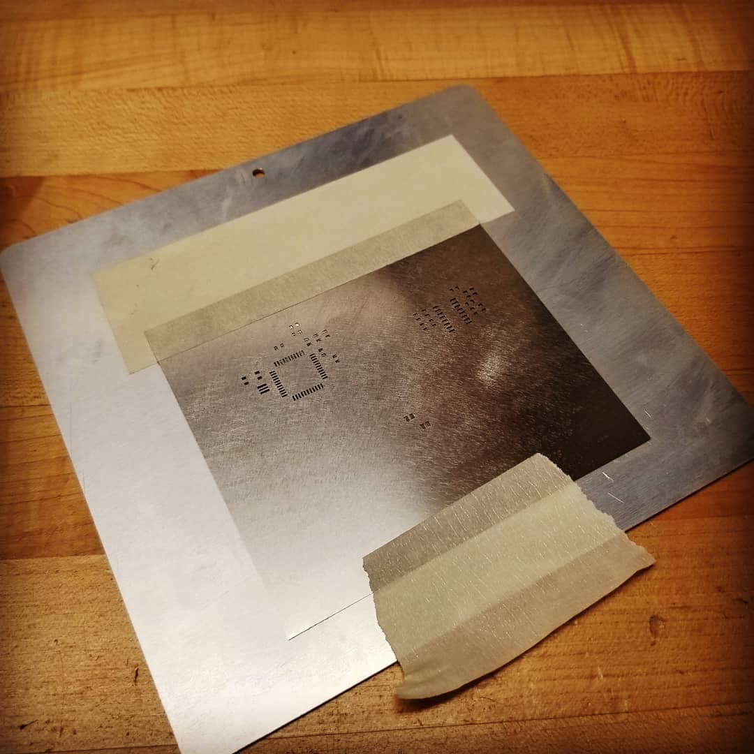
Stencils were used to apply the solder paste for the reflow process.
 |
 |
 |
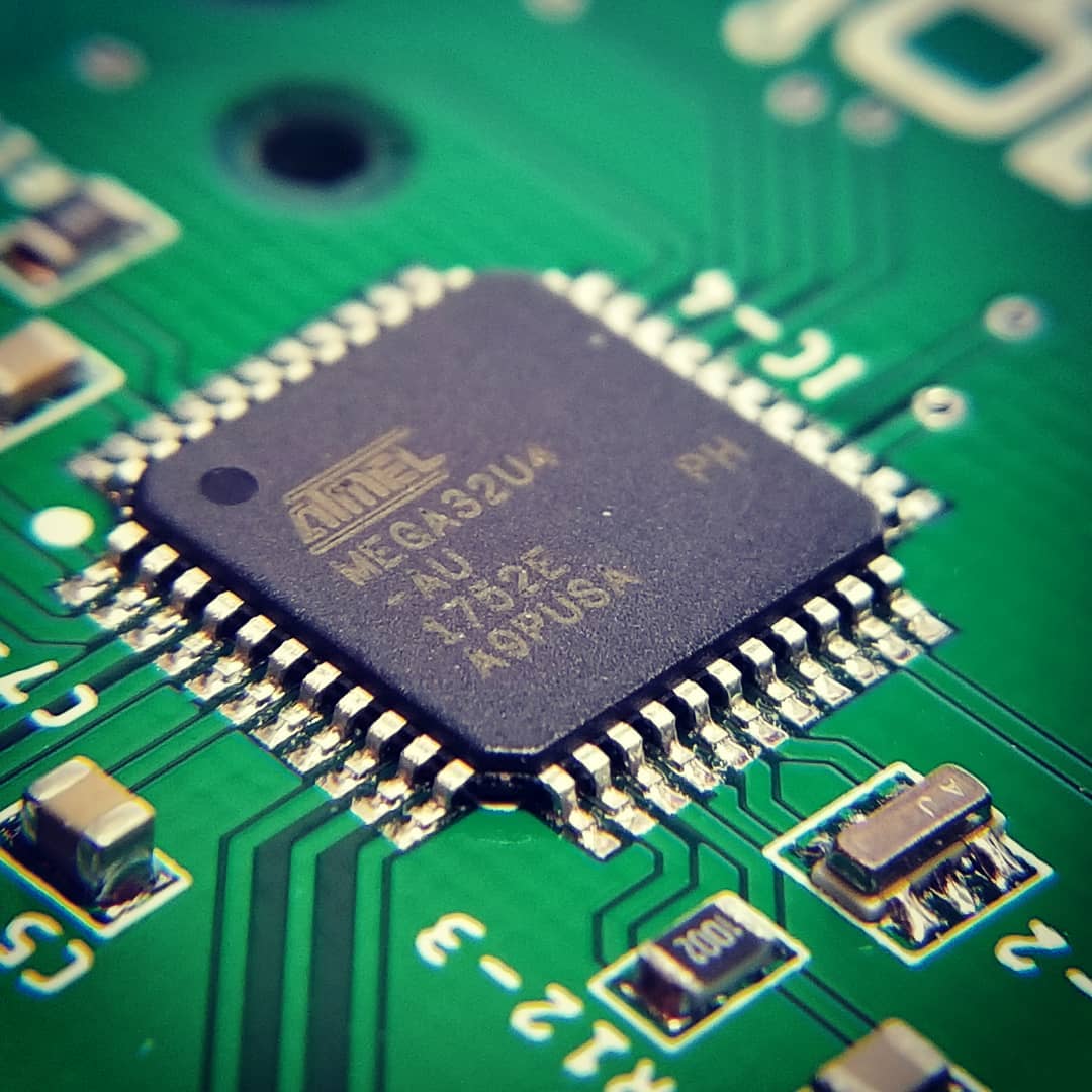
Close up of IC's after reflow process.
 |
 |
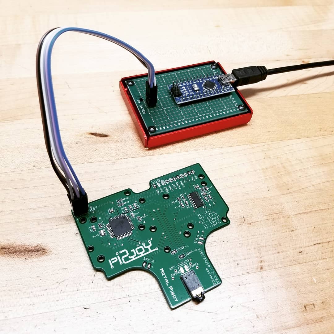
Control and power PCB soldered and ready for programming and initial testing.
 |
 |
 |
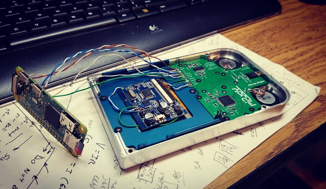 |
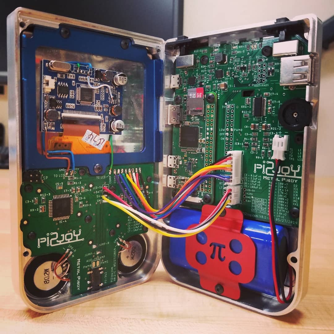
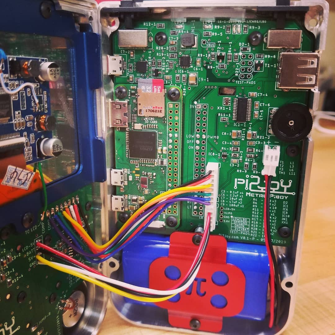
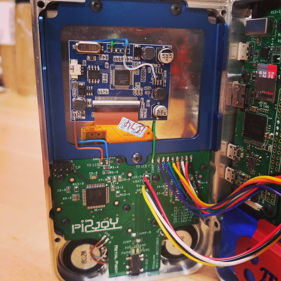
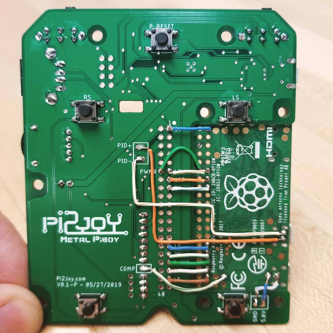
Final assembly:
The Raspberry Pi Zero W sets on top of the power pcb and wires get soldered on the back side to keep everything nice and neat. I decided on the short wire method so the Pi can be removed later used used for a different project if needed.
 |
 |
 |
 |
 |
 |
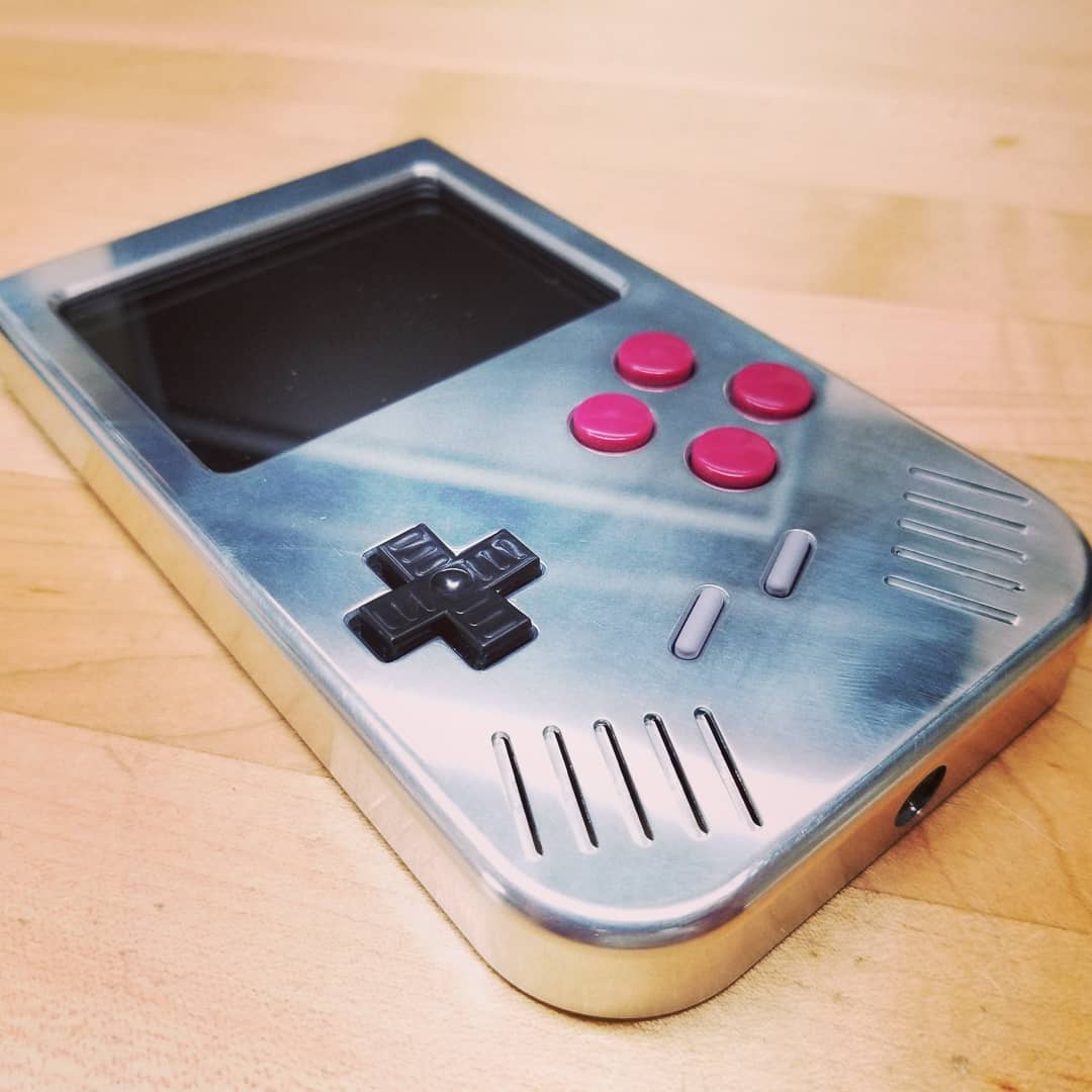
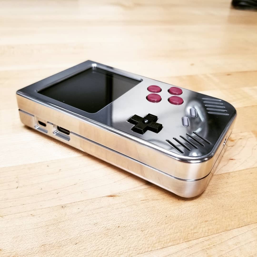
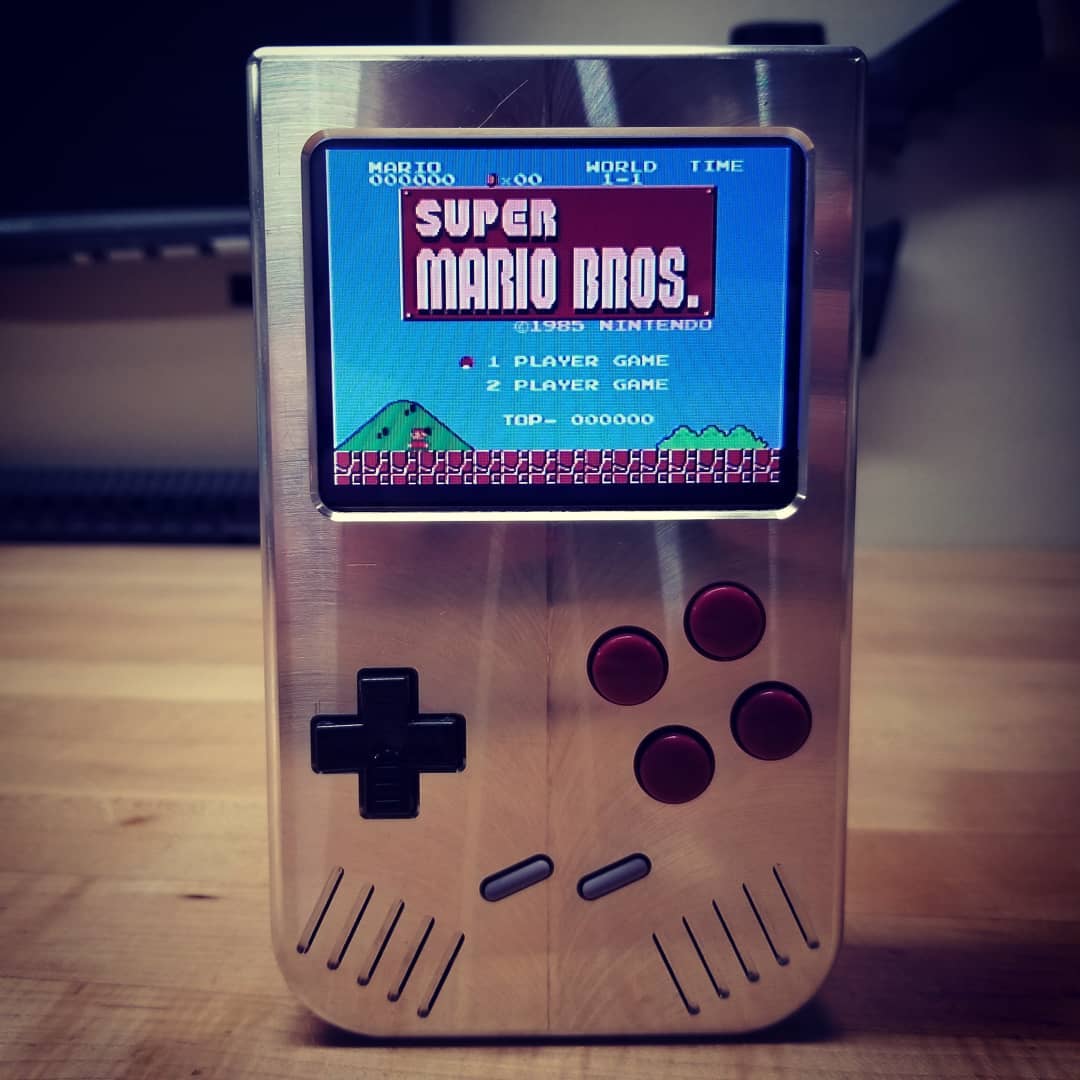
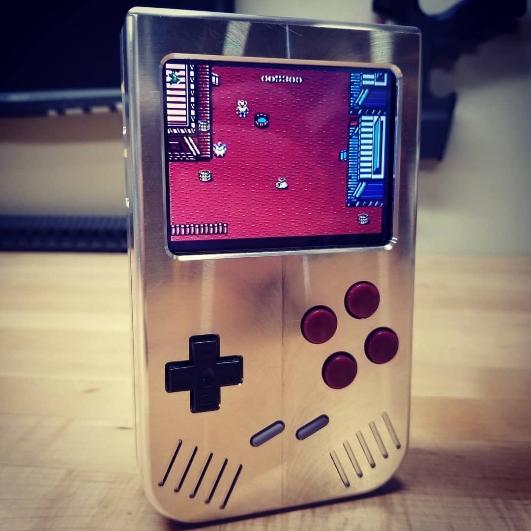
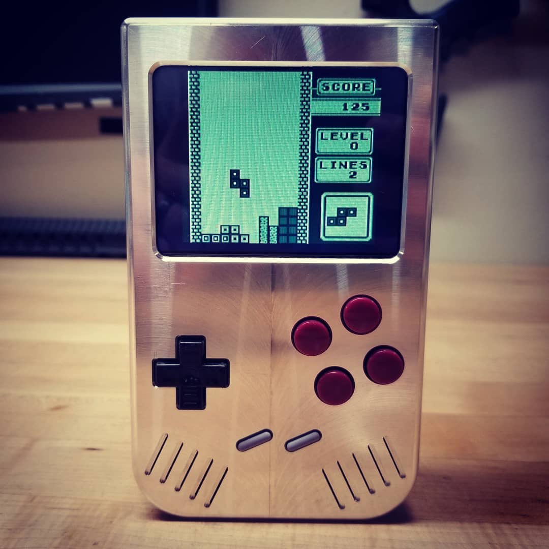
IT WORKS!!!
So excited to see the Metal PiBoy powered up after working on it for the past 7 months.
 |
 |
 |
Added Engraving:
I was debating when to do the engraving. My original thought was to machine the housing, apply finish (anodize, wet paint or powder coat) and then mechanically engrave through the finish coating to expose the aluminum surface below to give it a 2 tone effect. But since this is the "Metal PiBoy" I've decided to leave it silver for a more metal look. I will probably clear anodize the housing and maybe paint fill the letters to give it some contrast. On the top of the back housing I engraved the switch labels and also what the LED's indicated.... power, low battery, charging status. The charging status will share the position depending on if it's charging or fully charged. The LED colors are as follows: power = blue; low battery = red; charging = yellow; charged = green.
 |
 |
 |
Order yours now. Only producing 100 units.
Visit the following link for ordering info Metal PiBoy Pre-Order